Notch Filters
Cuthbert Nyack
Notch filters are used when it is necessary to remove a
"single" frequency from a signal.
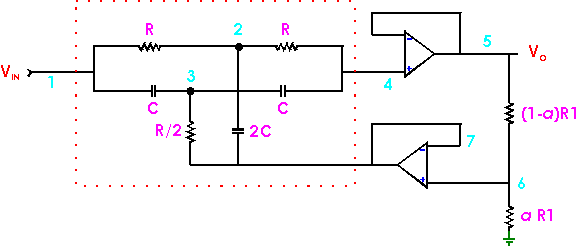 In the above circuit the transfer function is:-
Vo/Vin = (s2 + w2)
/(s2 + 4 w (1-a) s +
w2) with w = 1/(CR)
Without feedback a = 0 and one is left with the transfer function of the
twin T by itself(shown within red dotted rectangle).
Without feedback the Q is small(1/4). The inclusion of
feedback by the opamps results in a variable Q for the circuit and Q
can be made large.
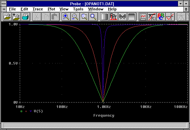
The above output shows how the selectivity changes with a. For above plots a=0.09, 0.67,
and 0.97.
In the literature a circuit for a narrow band notch filter is commonly given as
the above circuit with the feedback opamp removed (5 connected directly to 7).
A circuit for a tunable notch filter is shown below. R1 = R2 = R3,
R4 = R5 = R1/2. Circuit is tuned by C1 and
resonant frequency is 1/R4(C1C2)½ rad
s-1.
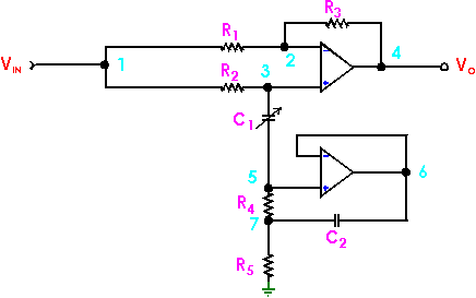 A simulation of the circuit is shown below. R1 = R2 = R3
= 80k,
R4 = R5 = 40k,
C2 = 1uF, and plots are for
C1 = 50,100,300 and 500pF.

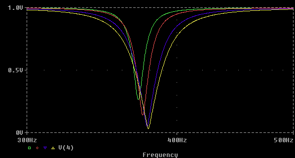
The effect on the Q of varying C1 (50pf green to 500pf yellow) while
changing C2 to keep the frequency "constant" is shown below.
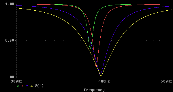 Result of varying C1 (same values as above) and adjusting R4 to keep the
frequency constant is shown below. The relations between the resistors are
maintained.
Return to main page
Return to page index
COPYRIGHT © 1996 Cuthbert A. Nyack.


